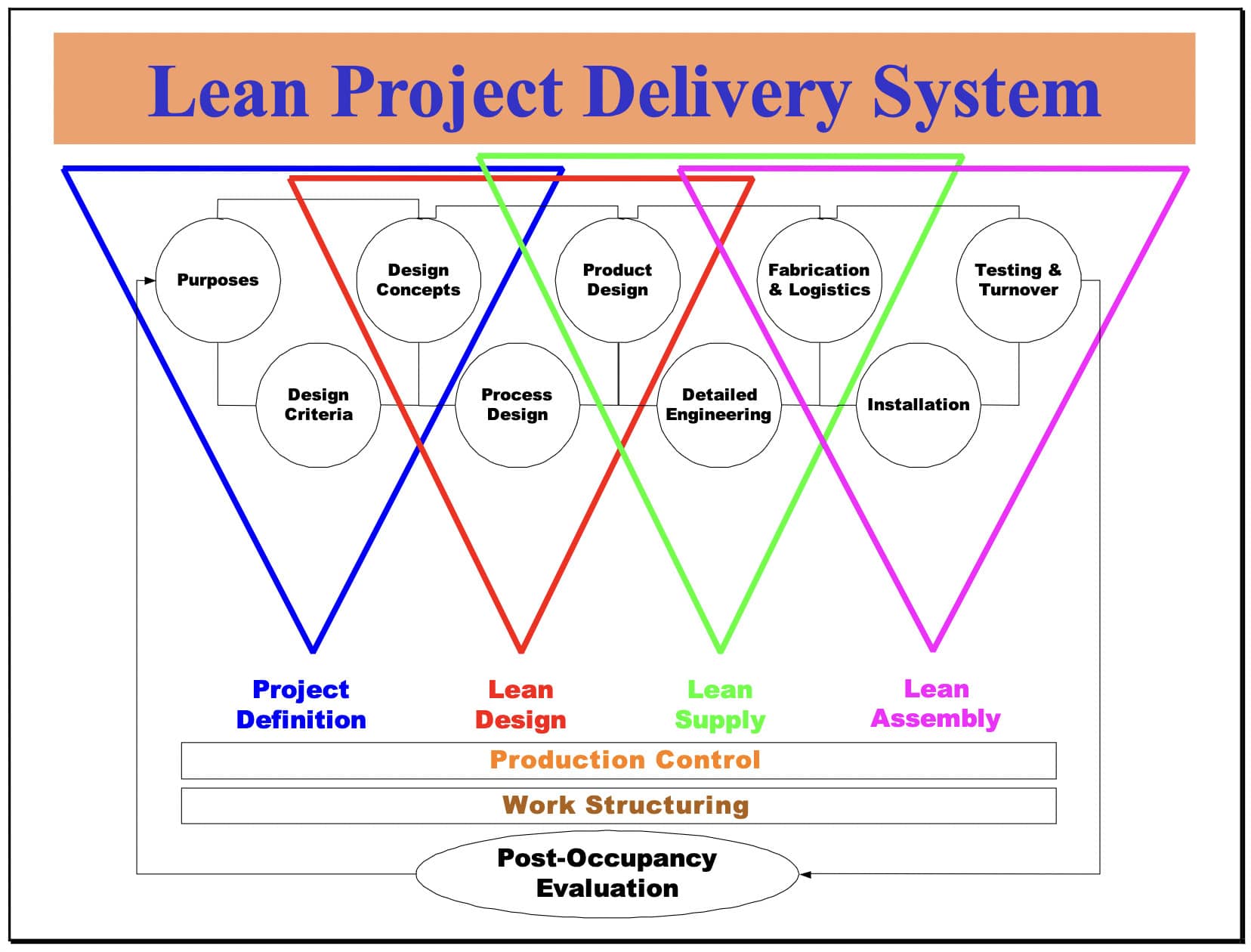
Within the Lean Project Delivery System, the Lean Design phase begins once Project Definition has aligned purposes, criteria, and concepts. It ends when product and process design have been produced and themselves brought into alignment with the Project Definition elements.
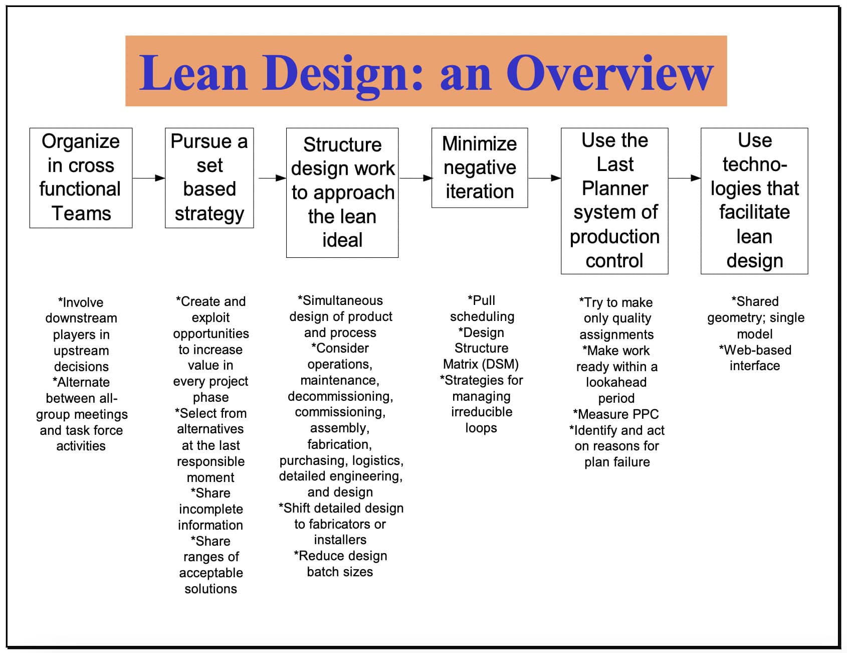
LCI has been developing a lean approach to the management and execution of design. What we have so far is summarized in Figure 2. In rough order, the steps are to:
Organize in cross functional teams
Pursue a set based strategy
Structure design work to approach the lean ideal
Minimize negative iteration
Use the Last Planner system of production control
Use technologies that facilitate lean design
In the lean construction community, production is understood as an integrated process of designing and building, which is at the heart of Lean Design. However, designing and building are very different.
-
Designing produces the recipe and Building prepares the meal. This is the ancient distinction between planning and doing.
-
They also differ in the concept of quality appropriate to each. Design is judged ultimately against its fitness for use; the extent to which it realizes the purposes of those for whom the product is being produced. On the other hand, the product itself is judged by its conformance to the geometry and specifications expressed in the design
-
Variability of outcomes is undesirable for Building--consistent with the concept of quality as conformance to requirements. However, if design products were entirely predictable, the design process would not be adding value.
-
Fourth and last, iteration in Building is rework; clearly a type of waste to be avoided. By contrast, designing often requires the production of incomplete or provisional outputs in order to develop understanding of both design problems and alternative solutions.
Designing can be likened to a good conversation, from which everyone leaves with a different and better understanding than anyone brought with them. How to promote that conversation (iteration), how to differentiate between positive (value generating) and negative (wasteful) iteration, and how to minimize negative iteration are all critical design management skills.
The tools and techniques listed below are available for managing and producing design within the Lean Project Delivery System. Some of the tools are more strategic. Others are more tactical. All are in process of development. Cross Functional Teams, Pull Scheduling, and Work Structuring are used in all project phases and are described in other LCI White Papers, so only their role in design will be discussed here. Last Planner is not discussed at all, application to design having been covered extensively in other publications2.
-
Cross Functional Teams (see LCI White Paper #9)
-
Pull Scheduling (see LCI White Paper #7)
-
Reduce design batch sizes
-
Design Structure Matrix
-
Strategies for Minimizing Negative Iteration
-
Set Based Design
-
Share incomplete information
-
Work Structuring (See LCI White Paper-5 and Tsao et al. (2000) “Case Study for Work Structuring: Installation of Metal Door Frames”. Available at www.sussex.ac.uk/spru/imichair/iglc8/index.html)
-
Simultaneous product and process design
-
Shared geometry; unified modeling
-
Shift detailed design to specialty contractors
-
Produce and inspect outputs based on a definition of quality as’ fulfillment of purpose’, not ‘conformance to requirements’
-
Last Planner system of production control
Cross Functional Teams
Cross Functional Teams are the organizational unit for all phases of the Lean Project Delivery System. All stakeholders need to understand and participate in key decisions. However, it is not possible to do work in perpetual mega person meetings, so some division of labor is required. In general, the appropriate pattern to follow is alternation between bigger alignment meetings and work by individuals and smaller teams on the tasks identified and agreed in those meetings.
In the design phase, the natural division is between product and process design, but the trick is to counteract the developed tradition of producing them separately and sequentially. Information technology can be helpful by making the state of both more visible; e.g., through shared, integrated models. But having representatives of each relevant speciality assigned to each team will always be essential.
Pull Scheduling
Pull Scheduling is really a tool in the Work Structuring toolbox. It is used to do team planning, aka process design. In the Lean Design phase, the plan produced is ultimately for the entire design process. However, the technique can be used by teams of any size to further detail the work for which they are responsible.
Reduce Design Batch Sizes3
All too often specialists transmit completed design information with little regard for the needs of other team members and downstream customers. Design decisions and outputs are grouped(batched) in traditional ways that were developed when designing and building were not integrated, and when each discipline tended to practice a throw-it-over-the-wall, sequential processing of project information. What is needed is to divide design outputs and communicate them more frequently to release other design work. Typically, this produces smaller batches and speeds up the design process. Since the set-up time to review design information is short for engineers who are up-to-date with the status of a design the penalty for batch size reductions is very small and does not negatively affect the design processing capacity of a team. Rather the opposite appears to be true. The set-up time and the work-in-process inventory become quite large if the batch size of design information is increased. In addition to dividing design decisions and outputs into smaller batches, it is also necessary for the various specialists to learn how to communicate incomplete information without misleading their co-workers. The mechanical engineer may be very happy to hear that heat loads may change. She can decide to defer other decisions or perhaps choose potential redundant capacity if there is no time for waiting. Currently, both tradition and fear of liability constrain the free flow of information among designers and engineers.
Design Structure Matrix
Lottaz et al. (1999) tell a story illustrating negative (needless) iteration. Holes for refrigeration conduit were required in a beam (Figure 2). Primary dimensions were: 'd' (the diameter of a hole), 'e' (the distance between holes), 'x' (the distance from first hole to column), and 'h' (the depth of the beam).
The architect first specified values for the four dimensions then sent an annotated drawing to the steel fabricator, who changed the values for e and x and sent it on to the engineer. The engineer reduced the diameter of the hole (d) and sent the document back to the architect.Perhaps in a fit of pique, the architect reduced the value of x from 1100 mm to 1000 mm and finally involved the HVAC subcontractor, who made further changes. The cycle of changes and transmissions continued. The erection contractor was running out of time, so fixed values for the dimensions and had the beam fabricated. Unfortunately, he was then unable to persuade the team to accept his solution. The result was considerable time and money lost on the project.
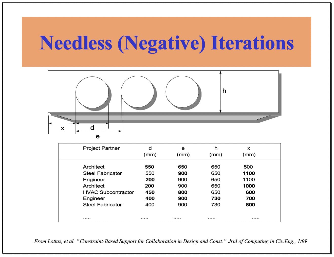
The beam penetration case is an example of negative iteration; i.e., iteration that could have been avoided without loss of value. Occurrences like this are all too common because of the multiple criteria any one design must meet, and the tradition of sequential processing, aka ‘throw it over the wall’.
Production of a pull schedule by a cross functional team is the first thing to do to minimize negative iteration of this sort. After further detailing of required inputs for the activities included on the pull schedule, the Design Structure Matrix (DSM) can be used to minimize iterative loops. DSM is incorporated in prototype software LCI has produced in conjunction with Loughborough University. The combined software is called DePlan (short for Design Plan) and consists of a front end planning tool called ADePT and a version of Last Planner production control called ProPlan. This software is available currently for experimental use by LCI contributors and others whose involvement can advance the research.
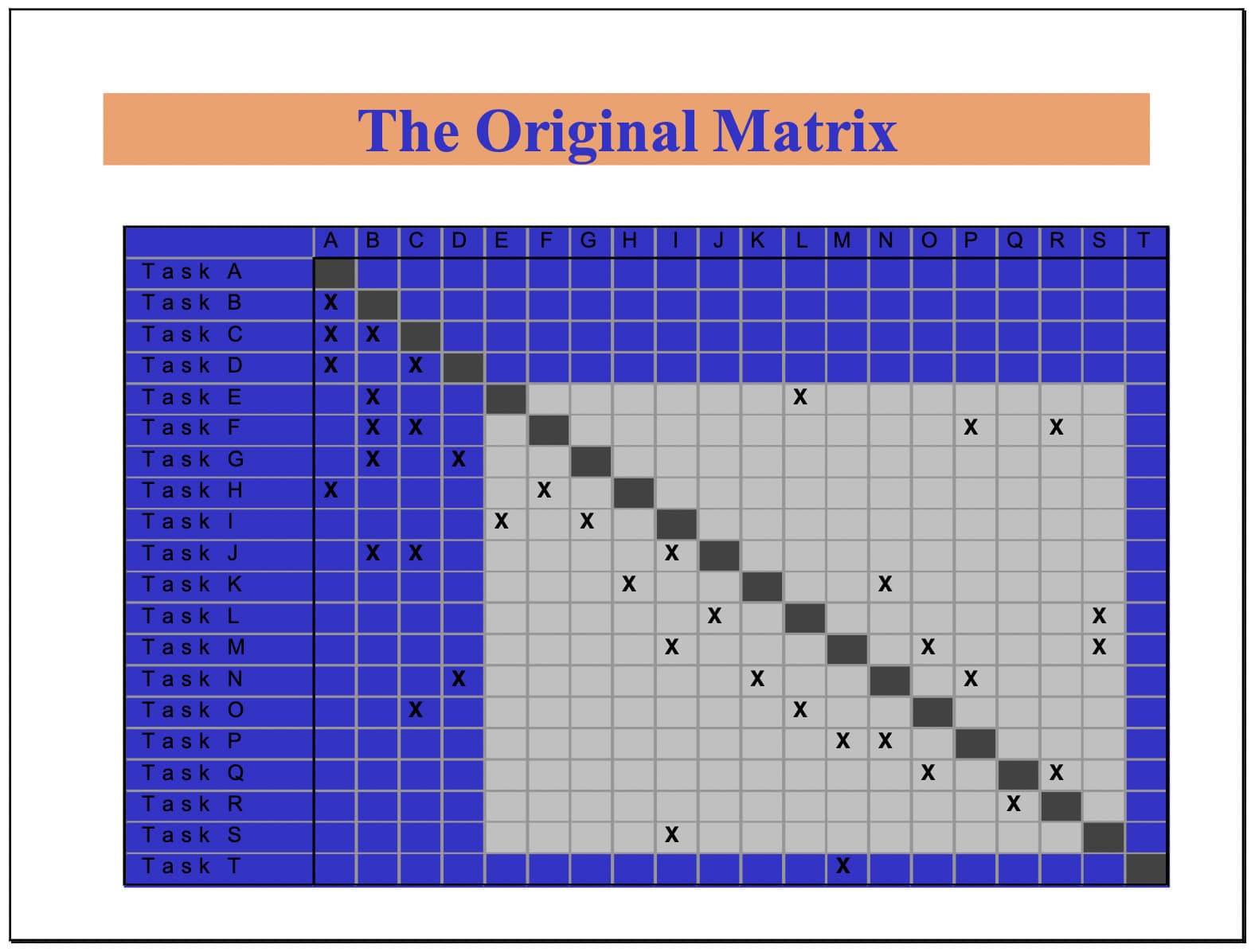
The pull schedule will have sequenced design tasks in some way. In the matrix above, tasks are given letters indicating their place in the original sequence. An x in the matrix indicates that the task in the vertical list is dependent upon the task in the horizontal list. For example, Task F is dependent upon Tasks B, C, P, and R. Since B and C are currently scheduled to be done before F, they pose no problem. However, Tasks P and R are currently scheduled to be done after F.This dependency loop is common in design because of the complexity and interdependence of design decisions. However, the size of such loops can be reduced through use of the DSM software.
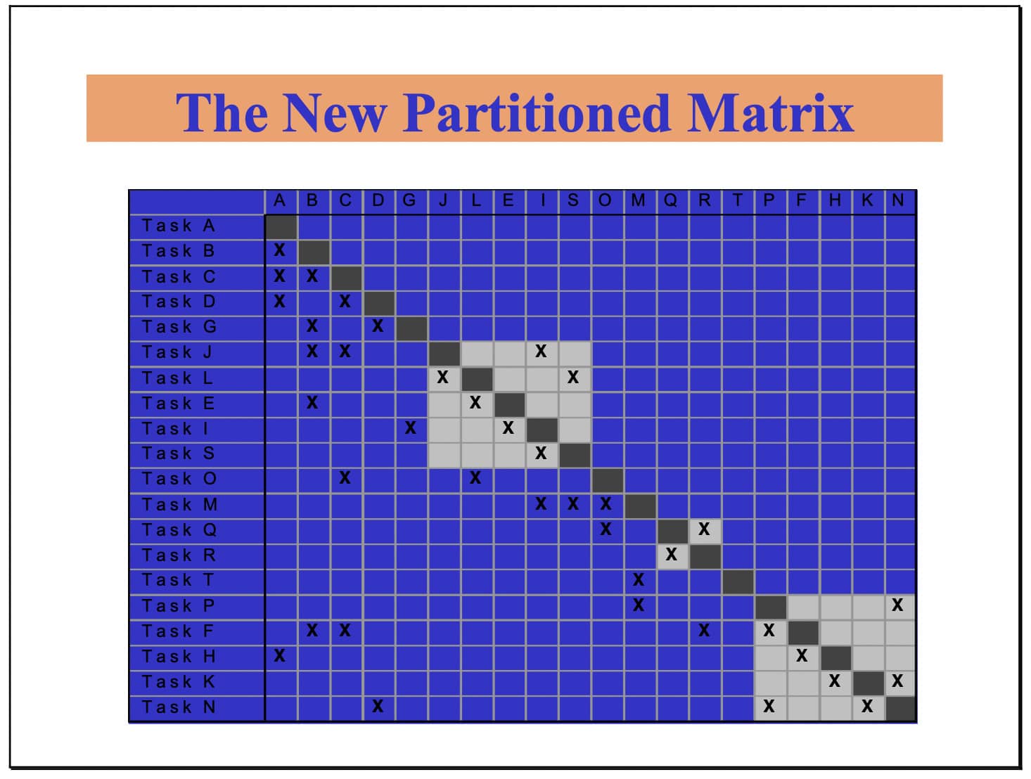
DSM contains an algorithm for resequencing tasks to minimize looping. After running the software, a new matrix (shown above) is produced with smaller loops. We suspect that DSM may be used many times over, along with redefining tasks, in order to come to an acceptable design schedule. That schedule will almost certainly contain some loops but they will be smaller and more manageable.
Strategies for Minimizing Negative Iteration
The first strategy for minimizing negative iteration is use of pull scheduling and DSM, plus reorganizing the design process as indicated below. Once irreducible loops have been found, they are jointly assigned to the relevant teams of specialists.
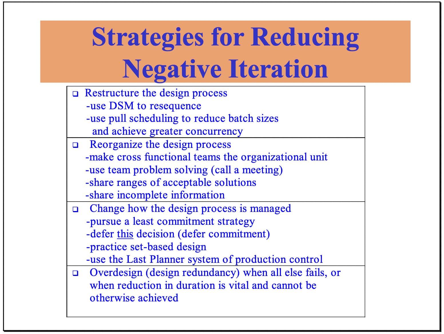
Those teams must then decide how to manage their interdependent tasks. General strategies that govern all design activities include use of the Last Planner system of production control and practicing Set-Based Design. Specific strategies for managing iterative loops that have thus far been identified include:
-
Hold a team meeting to accelerate iteration
-
Defer final completion until some critical items of information have been acquired
-
Design to the upper end of an interval estimate; e.g., design a structure so it will hold the maximum load that might be placed on it
Set Based Design
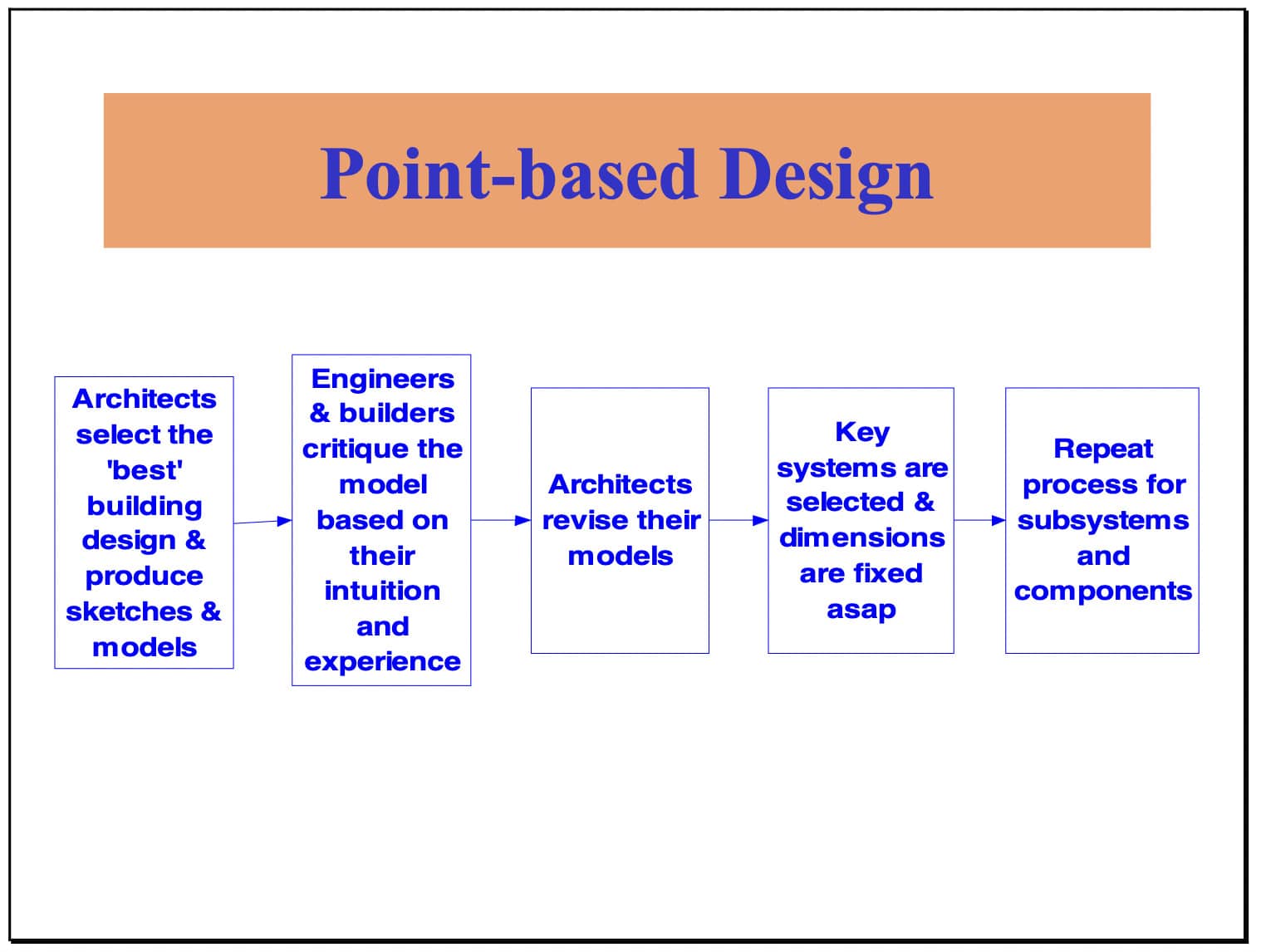
"Set-based engineering" has been used to name Toyota's practice of a least commitment strategy in its product development projects5. That strategy could not be more at odds with current practice, which seeks to rapidly narrow alternatives to a single point solution, but at the risk of enormous rework and wasted effort. It is not far wrong to say that standard design practice currently is for each design discipline to start as soon as possible and coordinate only when collisions occur. This has become even more common with increasing time pressure on projects.
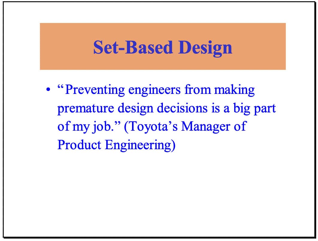
Toyota is a leader in product development, just as they are in factory production. Toyota's Manager of Body Engineering expressed their perspective well when he said that his job is top prevent premature decision making. Toyota's product development process is structured and managed quite differently even than other Japanese automobile manufacturers.
Toyota’s product development:
-
Develops multiple design alternatives.
-
Produces 5 or more times the number of physical prototypes than their competitors.
-
Rejects changes that expand, rather than contract, the space of possible designs.
-
Puts new products on the market faster than their competitors.
In all design processes, alternatives are generated, evaluated, and selected. It is common practice to select the best alternative as quickly as possible, then proceed to the next level of detail or decision and repeat the process. Why might this be common practice? Some typical comments that indicate current thinking:
-
Why waste time on designs that will not be used?
-
We don’t have time to carry forward multiple alternatives.
-
Why wait to decide if the best alternative has been identified?
These reasons for practicing point-based design seem plausible, but raise the questions:
-
How is it that Toyota "wastes time" on designs not used and yet develops new products faster and cheaper (in development costs) than their competitors?
-
How do we decide when we have or do not have time to carry forward multiple alternatives?
-
How often can we identify the best alternative immediately, without the benefit of further detailing and development?
We suspect that Toyota's superior performance is a result of reducing negative iteration, and that the reduction is more than sufficient to offset time "wasted" on unused alternatives.
As regards having the time to carry alternatives forward, that would seem to be a function of understanding when decisions must be made lest we lose the opportunity to select a given alternative. We need to know how long it takes to actually create or realize an alternative. Understanding its variability, we can add safety-time to that lead-time in order to determine the last responsible moment6. Choosing to carry forward multiple alternatives gives more time for analysis and thus can contribute to better design decisions.
Principles of SBD:
-
Map the design space.
-
Integrate by intersection.
-
Establish feasibility before commitment.
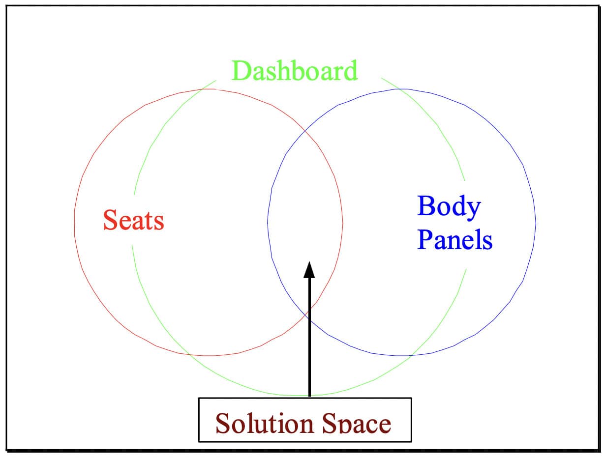
Mapping the design space is identifying the set of alternatives or range of values to be carried forward. All design contributors are freed to develop their work, as long as they stay within those boundaries; i.e., within that 'design space'. Integrating by intersection means looking for solutions within the intersections of sets or intervals. For example, various interface dimensions can be specified for mating components such as seats, dashboards, and body panels (see Figure 9). The search for solutions is focused on the shared values for those dimensions. Establishing feasibility before commitment refers to the obligation of a design contributor to maintain consistency with the preexisting design. This is radically different from point-based design, in which each design contribution may invalidate all previous work. As an example, consider the beam penetration case presented above.
SBD is said to have many benefits: The following list is drawn from the papers by Ward and Sobek:
-
Enables reliable, efficient communication. - vs. point-based design, in which each change may invalidate all previous decisions.
-
Waste little time on detailed designs that can’t be built.
-
Reduces the number and length of meetings.
-
Bases the most critical, early decisions on data.
-
Promotes institutional learning.
-
Helps delay decisions on variable values until they become essential for completion of the project.
-
Artificial conflicts and needless iterations of negotiations are avoided.
-
The initiator of a change retains responsibility for maintaining consistency.
Share Incomplete Information
Functional specialization, sequential processing, and fear of liability drive designers and engineers to share work only when it is completed. Concurrent design requires just the opposite:frequent and open sharing of incomplete information so each player can make better judgments about what to do now. Information technology will go some way towards enabling such sharing, but the key obstacles will be old habits of thought and action. Education, frequent reminders, and ultimately successful experiences will be necessary in order to promote open sharing. Of course, it will remain necessary to properly categorize the status of information that is released. If you are considering a design concept, that is very different from releasing a model or sketch which is to be the basis of others’ work. Until the new culture is developed, it seems prudent to attack that development within the optimum conditions provided by collocated teams dedicated to working together over multiple projects.
Work Structuring
In the LPDS, the intent is to structure work in pursuit of the lean ideals; i.e., to deliver what the customer needs, to deliver it instantly, and to deliver it without waste. Such a structure must anticipate every delivery phase; i.e., how the product is to be commissioned for operation and use, how the product is to be assembled, how the components are to be procured and fabricated,how the supply chains providing those components are to be configured, and how to structure commercial arrangements so that the relevant stakeholders and experts can be involved in making those decisions. All these ‘process’ considerations (and more) have to be determined in intimate conjunction with product design.
The purpose and complexity of work structuring as conceived within the LPDS reveals the inadequacy of traditional work breakdown structures (WBS), which, being derivative from conversion thinking, share its assumption that work in its entirety can be broken into pieces and those pieces managed as if they were independent.
Work structuring is not itself a tool, but rather a purpose in the pursuit of which tools can be employed. Pull scheduling and cross functional teams are examples of two such tools. LCI has research underway to develop work structuring guidelines beyond advising that consideration be given to all the life cycle stages of the product being designed.
Simultaneous Product and Process Design
Integrating design of product and of process is a challenge. Basically this means to consider and decide how to build something at the same time as we consider what to build. The challenge is to overcome the tradition of first designing the product, then throwing it over the wall to someone else to decide how or if it can be built. Besides old habits, we have to overcome specialization and commercial models. Specialization is unavoidable, but we can do better at educating designers regarding process design criteria and at educating builders regarding product design criteria. As regards commercial models, even in design-build, it is now common to use design-bid-build with specialty contractors, which makes it impossible to involve them in the design process proper.
Shared geometry; unified modeling
A key support tool for simultaneous product and process design (and for work structuring in general) will be integrated product and process models; i.e., complex databases capable of representing product design in 3D and also capable of modeling the manufacturing, logistics,assembly, commissioning (startup), and operations of that product or its components. Such tools as IDEAS by Strategic Design Research Corporation have been developed for manufacturing applications and are now being applied to the built environment.
Designing within a single model has obvious advantages; e.g., minimizing interferences, visualization and exploration of alternatives, and the creation of a tool for use during post-construction operations, maintenance, and future adaptations. A halfway house is to collect design produced in various forms and input it into a single model.
3D modeling can be useful in project definition, design production, and detailed engineering.In project definition, models can be used like sketches to display alternative concepts. In design proper, models can be used to insure that the design of systems, subsystems, and components are adhering to interface specifications. In detailed engineering, the product can be built in the computer before being built in physical space and time.
Once specialists are involved early and organized by group technology they can then use the computer model as a tool to integrate and test components within facility systems and to verify the compatibility of various system architectures. The computer model then becomes a value generation tool that supports the real-time consideration of multiple concepts for each system and components. Rather than a more sophisticated form of drafting, the model becomes a tool for simulating the product (and increasingly the process as well), so that better decisions can be made. Ultimately, and perhaps not in the far distant future, we will learn how to design and build the project, process, and team in the course of modeling7.
Shift detailed design to specialty contractors
Specialty contractors are typically required to produce ‘shop drawings’; i.e., detailed instructions for fabrication and installation of materials and components. Design specialists may have previously produced instructions of their own, which most often are discarded by the specialty contractors, who start anew. A simple waste reduction strategy is to stop having design specialists produce detailed design. For example, if there is a mechanical engineer separate from the mechanical contractor, have that engineer produce only single line drawings of duct routing and let the contractor do the detailed routing.
Practice quality control based on a definition of quality as ‘fulfillment of purpose’, not ‘conformance to requirements
Project production can be abbreviated to the steps: 1) determine customer (and other stakeholder)purposes and needs, 2) translate those purposes and needs into design criteria, 3) apply those criteria to the design of product and process, then 4) purchase, fabricate, deliver, and install materials and components in accordance with that design. Value is maximized when needs are accurately determined and when those needs are maximally satisfied by the product produced and the process employed to produce it.
However, the industry habit is to inspect outputs in that sequence of steps against standards, assuming that those standards themselves have been properly established. For example, fabricated items are inspected against the detailed fabrication drawings and relevant specifications. What’s missing is reevaluation of the drawings and specifications against stakeholder needs, on the chance that conditions or knowledge has changed, or that a better idea emerges.
Opportunity to improve understanding of purposes and needs, design criteria, or design should be taken whenever doing so adds value. The operating assumption in current practice is that the process only flows one way, so it is almost impossible to make an improvement downstream once a ‘standard’ has previously been established.
Summary
The steps involved in lean design are:
-
Organize in cross functional teams
-
Pursue a set based strategy
-
Structure design work to approach the lean ideal
-
Minimize negative iteration
-
Use the Last Planner system of production control
-
Use technologies that facilitate lean design
Tools and techniques available for lean design include:
-
Cross Functional Teams
-
Set Based Design
-
Share incomplete information
-
Pull Scheduling
-
Design Structure Matrix
-
Strategies for Minimizing Negative Iteration
-
Work Structuring
-
Simultaneous Product and Process Design
-
Shared geometry; unified modeling
-
Shift detailed design to specialty contractors
-
Produce and inspect outputs based on a definition of quality as’ fulfillment of purpose’, not ‘conformance to requirements
-
Last Planner system of production control
Lean Design Research Projects
-
Speciality Contractor participation in predesign and early design (Ballard)
-
Doing exploratory research with Rosendin Electric, Southland Industries, and Gowan Mechanical.
-
Will develop proposals for funding from specialty contractor associations; e.g., NECA, MCAA, SMACNA, NRA
-
-
Descriptive research: design practice (Ballard and Michael Whelton, UC PhD student)
-
intent is to document current design practice
-
plan to work with Burt Hill Kosar Rittelman Associates in Pittsburgh, PA. Whelton is also working as an intern for UC facilities management studying the project definition and design processes on a campus renovation project.
-
will present findings in March '01 Research Seminar
-
-
DePlan implementation by member companies (Ballard and Michael Whelton, UC PhD student)
-
Participants thus far are Southland, Linbeck, Boldt, Gowan, and Mace (U.K.)
-
DePlan is a software package consisting of both ADePT, a tool for planning design projects, and ProPlan, a software incorporating the functionalities of the Last Planner system of production control for application to design.
-
Foci of the study will include
-
use of DSM to minimize iterative loops
-
development of strategies for managing iterative loops
-
application of Last Planner to design production control
-
-
Will present findings at March '01 Research Seminar
-
-
Case Study in Project Definition and Lean Design (Zabelle and Ballard)
-
led by Todd Zabelle at Barnes
-
UC student Changwan Kim will do literature survey and support. Next year this will become his PhD research topic
-
findings to be presented at March ’01 Research Seminar
-
-
Modeling uncertainties in CAD systems-in preproposal stage (Iris Tommelein)
-
Work Structuring-Cynthia Tsao (Cal PhD student working under Tommelein. Greg Howell isalso actively involved.)
-
Speciality Contractor involvement in the design of semiconductor facilities-Nuno Gil (PhD student working under Tommelein and Ballard)
-
Descriptive case studies of successful design-build projects from the perspective of lean construction (Ballard and Howell, with support from a PhD student to be named). -hope to work with DBIA
Footnotes
-
For a detailed description of the LPDS, see LCI White Paper-8.
-
See (1) Ch. 6 and Appendices A-E in Ballard (2000). The Last Planner System of Production Control. PhD thesis, Dept. of Civil Eng., U. of Birmingham, U.K.; (2) Koskela, L., Ballard, G., and Tanhuanpaa, Veli-Pekka (1997). “Towards Lean Design Management”. Proceedings of the 5th annual conference of the International Group for Lean Construction, Gold Coast, Australia. http://cic.vtt.fi/lean; (3) Ballard, Glenn (2000). "Managing Work Flow on Design Projects." Proceedings of the conference on architectural management, organized by CIB TG96 and the Dept. of Architecture at Georgia Tech, Atlanta, GA, May 19-20, 11 pp.; and (4) Ballard, Glenn (1999). "Can Pull Techniques Be Used In Design?" Proceedings of the Conference on Concurrent Engineering in Construction, Espoo, Finland, August, 18 pages.
-
From Zabelle & Fischer (1999). “Delivering Value Through the Use of Three Dimensional Computer Modeling.” Proceedings of the 2nd Conference on Concurrent Engineering in Construction, Espoo, Finland. August.
-
From Ballard (2000). “Positive and Negative Iteration.” Proc. 8th Annual Conference of the Int’l Group for Lean Construction. Brighton, U.K.
-
Ward, Allen, Jeffrey K. Liker, John J. Cristiano, and Durward K. Sobek II (1995). “The Second Toyota Paradox: How Delaying Decisions Can Make Better Cars Faster”. Sloan Management Review, Spring, pp. 43-61. See also: Sobek, Durward K. II, Ward, Allen C., and Liker, Jeffrey K. (1999). "Toyota's Principles of Set- Based Concurrent Engineering." Sloan Management Review, Winter.
-
There appears to be an opportunity for alternatives such as concrete and steel superstructures to compete on lead time. Shorter, less variable lead times would allow delaying design decisions to accommodate customer needs for late-breaking information, or could be used to shorten overall project durations.
-
This paragraph is from Zabelle & Fischer (1999). “Delivering Value Through the Use of Three Dimensional Computer Modeling.” Proceedings of the 2nd Conference on Concurrent Engineering in Construction, Espoo, Finland. August.