
Abstract
Ongoing analysis of efficiency in construction compared to other industries indicates construction continues to fall further behind. There are several reasons for this, but one that is most prevalent is the difference in approach to design and engineering between advanced industries such as aerospace, automotive, etc. and the construction industry.
Over the past several decades, advanced industries have used different processes, methods and tools to design and engineer their products. With the advent of ever-increasing computer power and network speed, artificial intelligence (AI), machine learning (ML), robotic process automation (RPA) and enormous data complexes fed by sensors, new and more effective ways to design and engineer will emerge, no doubt reshaping design and engineering as we know it today.
In this paper, the Project Production Institute (PPI) proposes an alternative approach for design and engineering of capital assets. PPI proposes Concurrent Digital Engineering as the framework forward.
Keywords: Operations Science; Concurrent Digital Engineering; Artificial Intelligence; Machine Learning; Automation
Introduction
What do design and engineering have to do with Project Production Management (PPM)? Design and engineering 1) are forms of production, 2) establish what physical production will occur, and 3) provide the basis for future knowledge bases such as digital twins.
The purpose of this paper is to introduce engineering and construction industry professionals to a completely different way to design and engineer based on developments in advanced industries including Aerospace and Automotive. This paper forms the basis for future papers that will explore various methods and processes introduced herein, including requirements engineering, systems engineering, production engineering, etc.
Nature of Design
We propose that design and engineering are never complete. Engineering is an ongoing process that takes many forms. In the case of an industrial processing facility, there exists the need for chemical process design / engineering early in the project, as is the need for civil, structural, mechanical, electrical, etc. engineering. But there also is the need for engineering during fabrication and assembly as well as for rigging during transportation and construction. This is called Production Engineering and much like manufacturing engineering, it focuses on the processes for making, transporting and installing. It focuses on how work will be performed.
It is also important to recognize that design and physical production are very different. The following are some examples of how they are different:
Design produces the recipe and physical production prepares the meal. This is the ancient distinction between planning and doing.
Design is judged ultimately against its fitness for use; the extent to which it realizes the purposes of those for whom the product is being produced. On the other hand, the product itself is judged by its conformance to the geometry and specifications expressed in the design.
Variability of outcomes is undesirable for physical production – consistent with the concept of quality as conformance to requirements. However, if design products were entirely predictable, the design process would not be adding value.
Finally, iteration in physical production is rework; clearly a type of waste to be avoided. By contrast, design often requires the production of incomplete or provisional outputs in order to develop understanding of both design problems and alternative solutions.
Current State of Design in Construction
For the most part, designers and engineers involved in the construction industry spend almost all of their effort on design of the product or, in the case of construction, of the asset. Little, if any, attention is paid to how a product or asset will be fabricated, transported, installed or maintained. When fabricators and specialty contractors are brought into the conversation, it usually is to review a design rather than to provide input prior to completing the design.
There is a good reason for this. For many decades, due to competitive bidding laws and requirements, design and construction were detached. In an effort to reduce risk and lawsuits, architects and engineers along with their attorneys and insurance companies, have long sought to separate product design and process design, or means and methods. This myopic uniformed view results in unnecessary cost, poor quality, increased risk of safety incidents and the very claims these entities desire to avoid.
This structure results in some negative implications. Examples include: drawings may not be to scale so dimensions shall be field verified, drawings are for intent only and fabricator or contractor shall prepare and submit shop drawings, shop drawings are reviewed for general conformance not approved, and the list goes on.
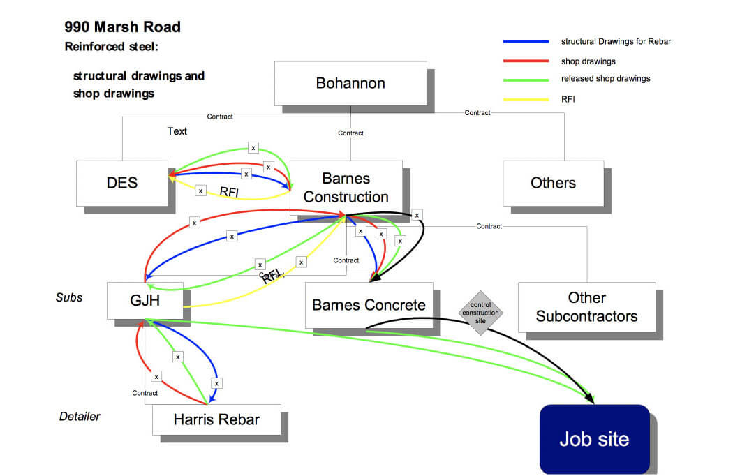
This results in a complex process integration and data management challenge for which construction management firms are more than pleased to attempt to manage for the owner for a fee. The following study conducted by Stanford University in 1999, illustrated in Figure 1, depicts the back and forth flow of design and detailed information related to reinforcing steel for a mid-size commercial building. It exemplifies the consequences of different participants in the design and construction process including the fragmentation of services providers as well as their use of different software and data models which do not easily exchange models or data between themselves. Each of the colors in Figure 1 represent a different format and model for the data pertaining to design and installation of steel reinforced concrete, used by a different participant – the architect, general contractor, concrete contractor, the rebar installation contractor (a subcontractor to the concrete contractor) and rebar detailer (a subcontractor to the rebar installation contractor). A complex exchange of requests for information and provision of data occurs simply because of 1) the fragmentation of service providers, 2) the separation of product design from process design (means and methods), and 3) the lack of a single unified software, model and format for the data needed to complete the task.
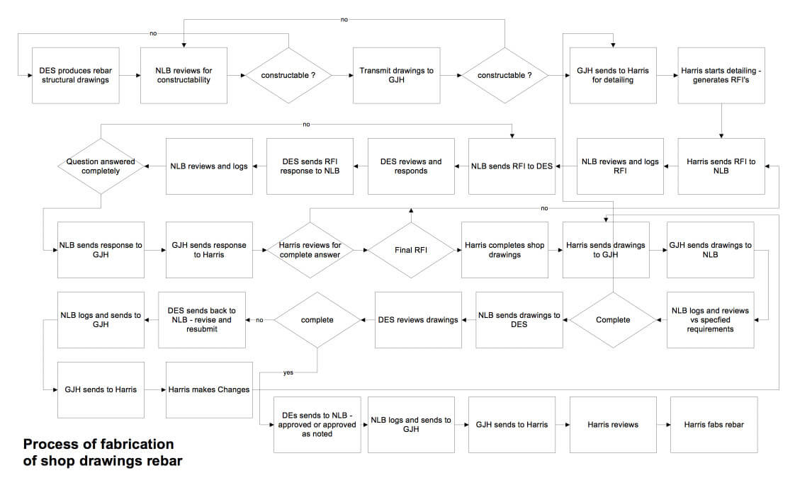
The length and complexity of the exchange is illustrated in Figure 2, which unwraps and lays out the sequence of enquiries and responses between different counterparties as they work to clarify the precise information and steps needed to complete the task of procuring and installing reinforced concrete according to the requirements specified. What results is a series of myriad iterations to update data in different formats about essentially the same task, simply because different stakeholders use different data models to describe particular aspects of the overall task. The consequence is much longer cycle time and significantly greater WIP to achieve a given task.
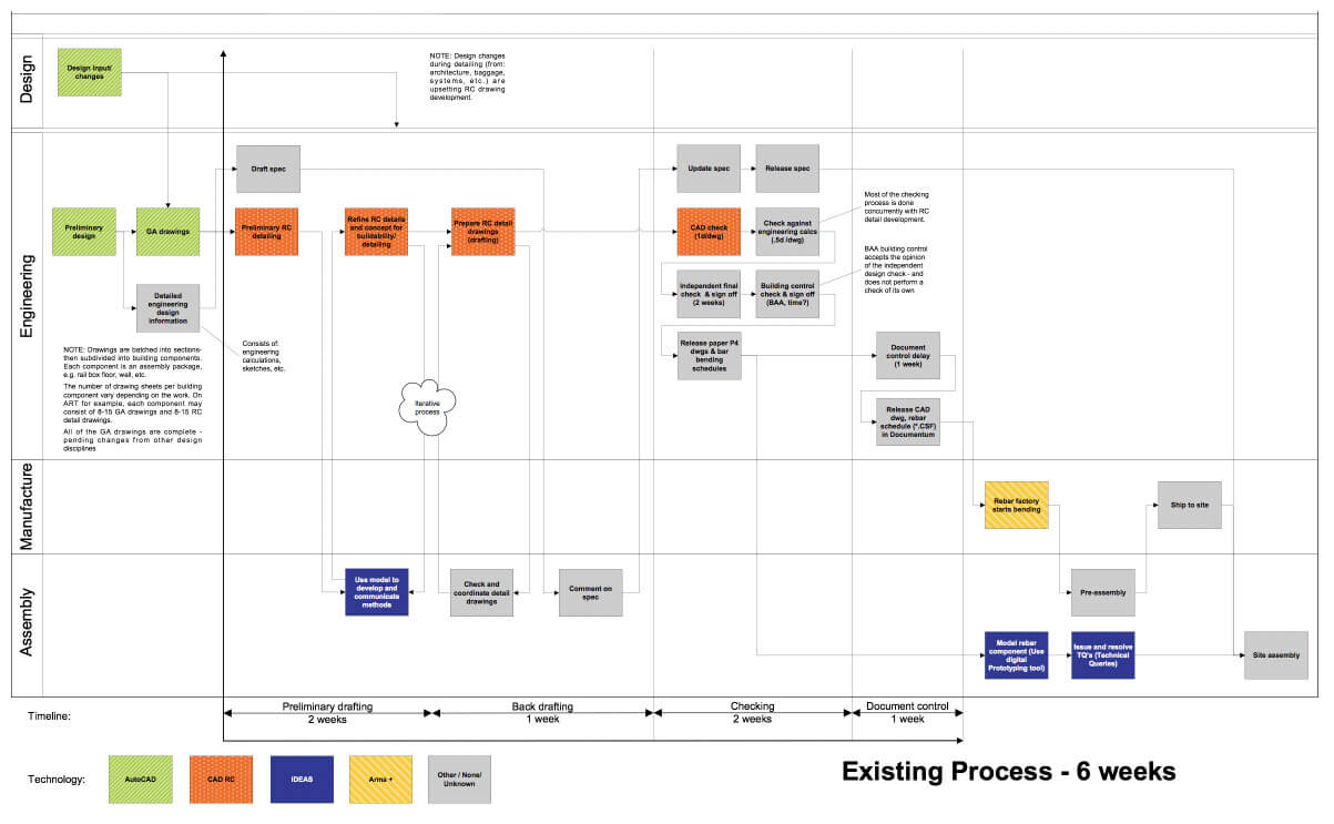
A second example, shown in Figure 3, is from a large civil engineering project in the United Kingdom. As the legend in Figure 3 shows, at least five different software applications, none of which exchange data easily with each other, are used by different players in design, engineering, manufacturing and assembly. Each piece of software deals with a particular aspect of design, manufacture, assembly and installation of rebar. As a result, a tremendous amount of rework takes place as five different data models are created and updated, albeit each model concentrating on a different aspect of the overall task. The overall consequence is the six-week cycle time reported in Figure 3 (which was compressed to five days including fabrication, transportation and installation).
What can we infer from these examples? Conventional design and engineering practices are focused on creating drawings and specifications of the product or asset for purposes of owner approval, permitting and purchasing including bidding or tendering. Designs are typically documented through narrative basis of design documents and symbolic 2D drawings.
The consequences of this approach are dire:
Processes for fabrication, transport, installation and verification (the how) are left downstream to fabricators and construction contractors to determine long after design is complete. Adapting designs to field constraints is costly and time consuming.
The typical design artifacts, documents and drawings are effectively analog in nature, resisting analysis for completeness, material quantity, cost and sequence, and must be used by field teams to drive procurement, transport, and installation design. Common tools used in the field for this are highlighter pens and radios.
The introduction of 3D computer modeling has helped resolve some of the barriers to evaluating designs for completeness, quantity, and scope, but its application is typically focused on design, and not used in support of production (fabrication, transportation, construction and commissioning). The reason for this can be traced back to the aforementioned separation of design from means and methods. One can only wonder why, with modern day 3D modeling capability and digital pads, drawings are even produced.
Equally surprising are the attempts at using Critical Path Method (CPM) scheduling [1] and earned value analysis as the means for coordinating and managing design and engineering workflows. These methods are not well suited to address the iterative nature of design and engineering, and yet project professionals attempt to use them anyway.
What can be Learned From Other Industries?
As the construction industry continues to debate whether a project should be engineering-led or construction-led, other industries have adopted a different answer: concurrency of engineering work execution.
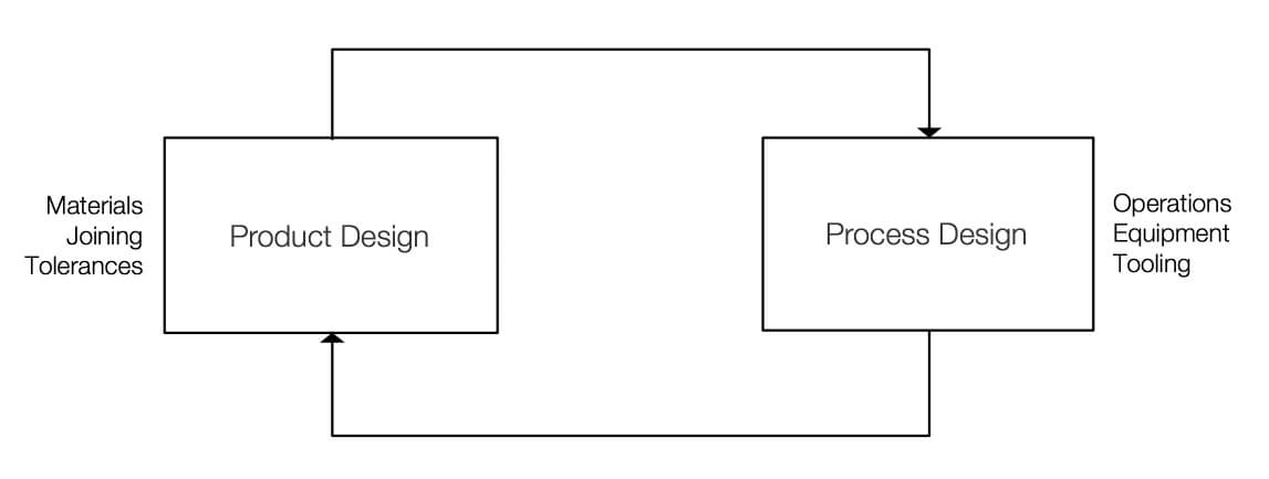
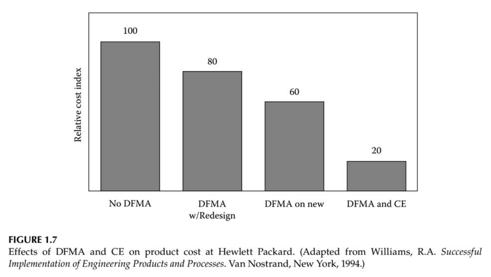
The automotive and aerospace industries offer a stark contrast to capital project design & construction practices. As market conditions became more complex and dynamic, new ways of design and engineering were needed. This resulted in the development of concurrent design and engineering, a work methodology emphasizing the parallelization of tasks (i.e. performing tasks concurrently), which is sometimes called simultaneous engineering or Integrated Product Development (IPD). This soon started to become digital dexterous yet heterogenous with the associated enabling processes, structures and technologies (3D modeling, 4D visualization, PD/LM, etc.) and team-based structures. Methods such as systems engineering and design for manufacture and assembly (DfMA) have proven to be of high value, as depicted in the following statement.
“It is now widely accepted that over 70% of the final product costs are determined during design.”[2]
Boothroyd, Geoffrey; Dewhurst, Peter; Knight, Winston A. Product Design for Manufacture and Assembly (Manufacturing Engineering and Materials Processing).[2]
With less emphasis on the lines between design, manufacture and assembly, these industries grew from artisanal craft-based efforts to globally distributed enterprises without enforcing a break – commercial, technical or otherwise – between designing and making. Three major gaps soon narrowed in data, the workforce and response times to changing conditions, which allowed certain innovators and manufacturing sectors to improve their position on projects, products and markets because of the ability to apply novel processes that would positively improve their outcomes and key results (OKRs).
Vertically integrated companies help, but more profound differences in culture, technique and technologies may be observed in action. Responsive networks are evidenced today where large institutions or legacy long-life product cycles have adapted and can react to changing external or internal variation because the level of specificity, measurements, auditability, reusability and traceability have improved dramatically. It has enabled concurrency of our work, inventory, and information flows. Appending the digital element to concurrent engineering to become Concurrent Digital Engineering (CDE) creates additional benefits in cost, flexibility, speed and performance.
Product engineers are a part of the design team, responsible for the “chunking” of designs into modules that may be fabricated, delivered and assembled in an optimal way. This ensures that existing manufacturing and assembly capacity is matched to design constraints or detailed requirements engineering and models can be verified and validated earlier and frequently promotes agility and transparency to change.
Industrial and systems engineering were brought together to create better outcomes of schedule, resources and quality. Looking back in history, industrial engineering is an interdisciplinary profession that is concerned with the optimization of complex processes, systems, or organizations by developing, improving and implementing integrated systems of people, money, knowledge, information, equipment, energy and materials.
For new developments, the product engineer ensures new approaches to manufacturing and assembly are conceived, tested and verified long before designs are finalized, ensuring the concurrent development of product and process. Culturally, it is standard practice for design teams to consider product and process in parallel, given the tight coupling between automotive & aerospace products and their ability to be built consistently at a desirable price.
The basis of competition shifts from product innovation to process innovation [3] [4] [5] [6] [7] [8], known as the Utterback effect. We have seen in industries such as automotive that some firms may focus on process innovation as a source of competitive advantage (for example, Toyota) while other firms choose a different strategy and continue to focus on design innovation (for example, BMW) [9]. Bringing the ability to adapt digitally through best practices in systems and software engineering allows entities to change with accuracy and precision.
Following is an introduction to various methodologies and processes that will improve the delivery of a capital project and, more importantly, the resulting asset.
1. Requirements Engineering
Requirements management plays a central role in the development process, for both business and compliance reasons. Explicit links between business and technical requirements back to discrete design solutions ensures traceability for quality and legal compliance (think FAA.) Verification and Validation of systems, subsystems and components is a critical technique used during design to avoid the need to complete design after manufacturing has begun, when the cost of change is significantly higher.
What Requirements Driven Engineering provides is a means to create and manage requirements in a structured manner so that they are unambiguous, atomic and testable. Good requirements detail what something should do but defer decisions about how it should be accomplished until the design phase.
Each layer of requirements is developed, agreed and verified before they are passed onto the next level of detail, to which they are traced. As the requirements evolve through this process, verification tests are developed. These are used to verify that the products developed are compliant with the requirements.
Typically, much of the specification, design, technical and regulatory requirements information exist in unstructured documents that are stored in a document repository or multiple repositories. In most cases the information is hard to find, there is little or no configuration management of the documents and there is little or no traceability among the information elements (e.g., regulatory or compliance requirements) embedded in the documents.
Software can decompose these typically long and complex documents into sets of requirements in a tool where the information elements in the documents can be managed in a structured manner and can be related together using formal linking mechanisms. The linking is critical to creating and managing high-quality, robust and consistent requirements as it allow analysis of the impact of a change to a design or specification. This analysis can be carried out to determine the true cost of the change before it is accepted.
2. Systems Engineering
The wider practice of integrating product, process, requirements, verification, and validation has evolved into the discipline of systems engineering. The international council for systems engineering (INCOSE) developed the Systems Engineering Handbook that offers many lessons, including the techniques used in aerospace and automotive for complex program delivery. NASA also has an excellent Systems Engineering handbook adapted to their mission-based organization and industry.
The ability to adapt and respond is a major benefit of systems engineering that considers the end to end life cycle as well as the elements that compose, influence and control the overall system.
3. Set-Based Design (SBD)
The typical design process involves the sequential pursuit of a perceived optimal technical solution. While teams may be interdisciplinary in makeup, they tend to converge on a singular design solution early in the process, especially with respect to engineering analysis. An alternative development practice commonly applied in the automotive industry is set-based design, where teams are not only multi-disciplinary, but pursue multiple technical solutions in parallel. They develop multiple designs for a single product, simultaneously, delaying decisions and convergence late into the development process to ensure the strongest designs are selected, from the holistic perspective of project delivery, not just satisfaction of design criteria.
Set-based design does not necessarily require additional resource, but the structured development of multiple scenarios. In practice organizations are able to reduce design durations, freeing up resources to pursue additional design sets. A common organizational barrier to set-based design is the volume of existing design WIP within an organizational system. Set-based design may be pursued without additional resources but requires careful evaluation and re-prioritization of existing design WIP.
How much WIP is in an organization’s design system, including total resource deployed may be significant at the program scale. The consequence of design WIP, similar to a production system, is to reduce throughput to unsatisfactory levels. Set-based design helps leverage design WIP and capacity to drive optimal designs, rather than the first design.
Principles of set-based design include; 1) Map the design space, 2) Integrate by intersection, and 3) Establish feasibility before commitment. Map the design space is identifying the set of alternatives or range of values to be carried forward. All design contributors are freed to develop their work, as long as they stay within those boundaries; i.e., within that ‘design space’. Integrate by intersection means looking for solutions within the intersections of sets or intervals. The search for solutions is focused on the shared values for those dimensions. Establish feasibility before commitment refers to the obligation of a design contributor to maintain consistency with the preexisting design. This is radically different from point-based design, in which each design contribution may invalidate all previous work.
SBD is said to have many benefits. The are examples drawn from Ward and Sobek [10] including the fact that SBD wastes little time on detailed designs that can’t be built, delays decisions until they become essential and artificial conflicts and needless iterations of negotiations are avoided.
4. Production Engineering
Perhaps the single most important missing discipline in the design of a capital asset is Production Engineering. Where conventional design and engineering efforts focus on what will be made or built, production engineering focuses on how parts, assemblies and modules will be built, transported, installed, and commissioned along with how maintenance operations will be accommodated. Production Engineering considers and determines how work will be performed during fabrication, assembly, transportation, installation and commissioning.
Numerous players in advanced industries have adopted Design for Manufacture and Assembly (DfMA) as a framework for doing Production Engineering.
It is important to acknowledge Production Engineering must always be done at some point in a project and the later Production Engineering is pushed into the project life cycle, the less ability to influence. For instance, potential options available during early concept design are far more plentiful than when a mechanic attempts to install something onsite.
5. Early Involvement of Specialists
Of course to leverage Production Engineering early in the process, specialists must be involved from the beginning. The early involvement of fabrication and installation specialists, typically specialist contractors such as steel fabricators or mechanical contractors, allows early identification of opportunities, constraints, and discussion of ‘how’ work will get done, at the same time that ‘what’ is to be built is developed.
The inputs of specialty firms are best captured through the use of model-based design. The appropriate modeling and simulation environment, typically described as MCAD (mechanical computer aided design), is central to the application of concurrent digital engineering.
CDE makes little distinction over who should develop an integrated product model that supports simulation of product and process. However, experience shows that in-house teams of specialist engineers are able to continuously develop design models that serve the wider organization, resulting in superior WIP datasets that continuously serve the project organization, rather than a more typical milestone-based exchange with outside design firms to produce output. Model-based systems engineering (MBSE) grew in popularity in the aerospace and automotive industry to provide a visual context complementing requirements engineering. This circles back to concurrent engineering and/or integrated product development models. MBSE is a Systems Engineering methodology that focuses on creating and exploiting domain models as the primary means of information exchange between engineers, rather than on document-based information exchange. The MBSE approach was popularized by INCOSE when it kicked off its MBSE Initiative in January 2007. Recently, the focus has started to cover aspects related to the model execution in computer simulation experiment, to further overcome the gap between the system model specification and the respective simulation software. The advances allow us to open the opportunity for artificial intelligence and machine learning to go beyond descriptive or predictive analytics and provide engineering and design teams options or patterns not apparent in traditional methods.
6. Continuous Integration
Many capital program owners have prescribed design milestones, or stage gates. Typically numbering from 3 to 8 in number, these gates are convenient from an invoicing perspective but detrimental to the quality of product design. Design integration, the practice of bringing the design artifacts from multiple disciplines into a singular environment for testing, simulation, and verification, occurs only as rapidly as WIP data is released, typically at or near each stage gate.
A radical change in design development is continuous integration across the design supply chain. Cloud-based version control systems, when implemented in the context of a wider concurrent digital engineering program, have driven 100,000X increases in WIP exchange across teams, companies and regions, enabling continuous integration and evaluation of product designs as they happen rather than at milestones. Milestone submittals are out-of-date as soon as they are issued, whereas WIP data is current and analyzable. Particularly in aerospace and defense, as the tactics in the field changed to more guerilla and terrorist maneuvers, it was important that collaboration was key in developing more sense and respond systems using the intellect of many versus a hierarchical approach in solution development and deployment. This new network architecture with agile practices allowed a responsive network that could adapt. Instead of trying to improve the forecasting model, which would always have a margin error, industries improved response times to changes in their environment.
Experience shows that deployment of a cloud-based version control system also provides transparency into the actual design team, typically much larger than anyone anticipates. Whereas a typical design process may involve meetings and discussion among 10-15 key principles with no visibility or interaction across tactical engineers, a concurrent digital engineering approach with the same teams may expose 300+ engineers participating in the design, enabling a level of integration, transparency and throughput not achievable in a conventional approach. The network effect of Metcalf’s law is exemplified producing more responsive and higher quality outcomes and key results (OKRs).
Use of continuous integration and focus on WIP allows the wider design team “in” on the design for feedback, with concurrent engineering teams in the 300+ headcount range. Culturally, there is less resistance to revising, optimizing and improving designs while they remain “WIP” status, versus milestone designs that may trigger change orders and reluctance to optimize designs.
7. Simulation and Visualization
Typically restricted to structural and thermal domains, the role of computer-based simulation is central to the effective deployment of concurrent digital engineering, with a wider focus on the multi-physics of the product as well as its fabrication, transport, installation and operation.
Computing resources and associated software now allow a level of simulation approaching reality, with industry increasingly relying on use of a product’s “digital twin” to evaluate design, construction and operational status. The ability to immediately allocate resources using a variable cost model allows us to deploy large simulation models but integrate optimization, statistical process controls, analysis of variance (ANOVA), linear regression, and artificial intelligence using machine learning. ANOVA is a collection of statistical models and their associated estimation procedures (such as the “variation” among and between groups) used to analyze the differences among group means in a sample. Operation sciences can be fully leveraged by turning data into information.
8. Target Cost
Designing to a target cost or value is another common method used in advanced industries. Unlike the construction industry where costs are estimated and updated as work progresses (and claims are resolved), advanced industries often set a target cost which becomes an input or constraint to the design process. Wherein the construction industry designs to cost (verb) advanced industries design to the cost (noun). Another example of PPI’s three Eras of project thinking. The construction industry myriad in Era 1 and 2 focus on predicting the cost outcome. Advanced industries select a sale price, deduct the required profit and then use the remainder as the target cost. There is no need for prediction or estimation of final cost. Estimation is only used to determine cost contribution by systems, sub-systems and parts within the target cost.
9. Enabling Digital Technology
Enabling technologies for product development in automotive and aerospace were developed long ago with product and process engineering in mind, resulting in approaches to geometric representation (i.e. drawings) that ensured manufacturability.
Early 2D CAD (computer aided design) systems were in development from the 1960s, with 3D CAD tools and resulting digital data used to manufacture cars from the 1970s. The 1980s, comparatively recently in the history of major capital projects, saw the first widespread use of solid modeling to represent complex assemblies of parts, and the start of several key players such as Dassault Systemes, UGC, SDRC, Autodesk, and PTC.
Several remain in the market today, with Dassault Systemes’ flagship software CATIA used to design nearly every car and airplane in the commercial market, UGC (now Siemens PLM) in widespread use in the industrial sector and PTCs products used widely in consumer product design.
In support of concurrent product and process design, integrated tools for process simulation and CNC manufacturing (computer numerical controlled) ensure a streamlined flow of information and data between the concurrent engineering team.
Software technologies have evolved in the past 40 years to provide a sophisticated range of tools in service to the concurrent engineering program. Hardware computing, dramatically better CPUs, and the recent explosion in GPU-based computing has led to a revolution in integrated simulation for structural, fluid and thermal analysis.
The role of computer-based simulation is now central to the effective deployment of concurrent digital engineering, with a wider focus on the multi-physics of the product as well as its fabrication, transport, installation and operation.
Computing resources and associated software now allow a level of simulation approaching reality, with industry increasingly relying on use of a product’s “digital twin” to evaluate design, construction and operational status well after a product has been installed in the field. This is accomplished through a closed-loop exchange of sensor data from the field with central product models, allowing owner teams increased visibility and predictability into product performance.
There is no doubt that emerging technologies including artificial intelligence, machine learning, robotic process automation and IoT will transform how design is done in advanced industries. Just as computers have already begun to replace humans when it comes to engineering analysis, digital pads and mixed reality are beginning to make physical drawings obsolete. These are but just two simple ways in which digital technologies are pushing the boundaries of design.
10. Production Control
Though not common in advanced industries, some form of planning and control of workflow is needed during design and engineering. Of particular interest is 1) the management of design process flow and iteration and 2) the allocation of capacity (engineers, computers, etc.).
Management of capacity is more complex in capital projects as result of the ratio of direct employees to contractors. For instance, one automotive company reported 85% of the engineering staff work directly for the company, the remaining 15% were either individuals employed as contractors reporting to company employees with a very small percentage proving third-party testing. This is in contrast to energy and industrial companies that made the decision to outsource engineering years ago. Technical people now work for engineering service providers who seek differing objectives for a project (make a profit, keep people busy, etc.) from the owner that is looking to create a product or asset.
Due to the complex and iterative nature of design, a real time distributed workflow planning and control system is needed.
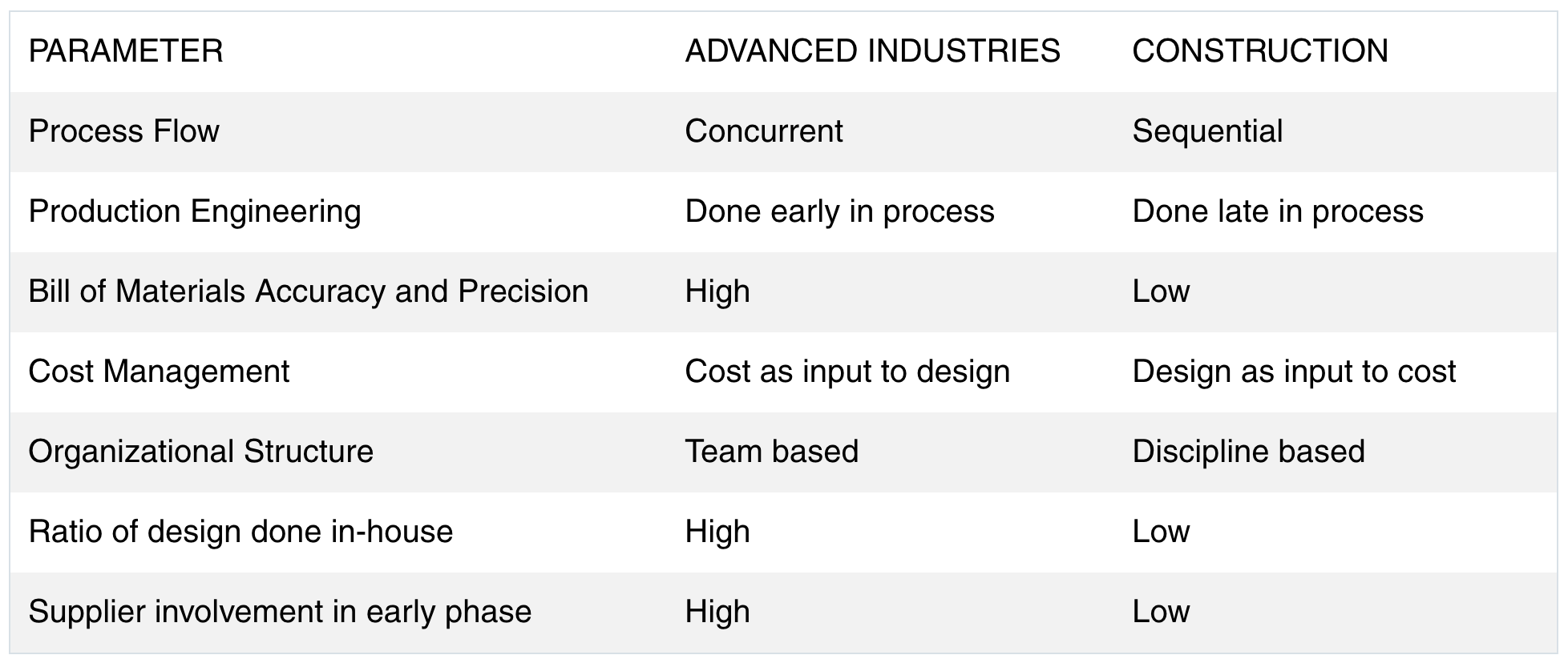
Design in Advanced Industries Compared with Construction
Table 1 compares the approach to design / engineering between advanced industries and construction.
Concurrent Digital Engineering for Capital Projects
As depicted in the graphic below, Concurrent Digital Engineering integrates concurrency of work processes and methods with enabling technology. Concurrent Digital Engineering seeks to simultaneously develop, integrate, verify and validate capital projects that comply with:
Performance requirements including technical, cost & time objectives
Fabrication, assembly and installation constraints
Operability performance and maintenance operations
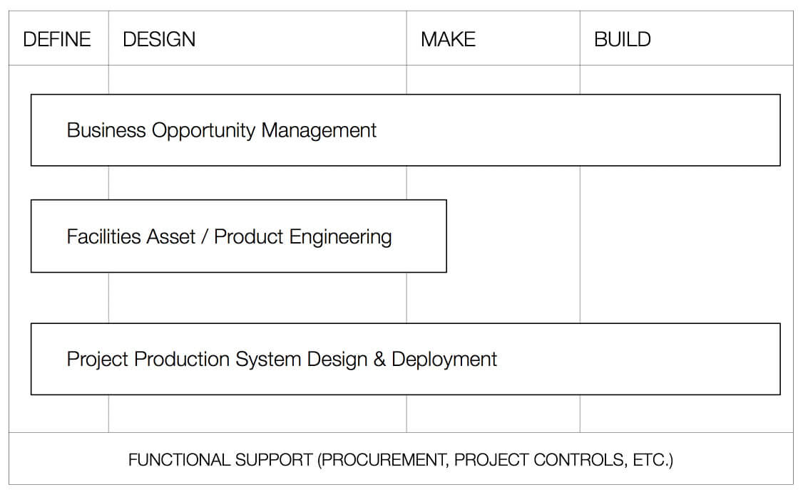
Figure 8 is a roadmap for the various technologies and methods that enable the full concurrency of execution of a program. PPI will call on various experts to publish articles describing the application of each of the methodologies and enabling technologies outlined herein.
Conclusion
We have compared design and engineering practices in advanced industries, such as aerospace, with the prevailing practices of the construction industry, arguing that the differences in practices and methods used is a major cause for the construction industry lagging in efficiency and effectiveness. We summarized a number of enabling technologies and methodologies, in routine use in advanced industries, that in aggregate enable concurrent digital engineering. Concurrent Digital Engineering promises a step change in improvement in project delivery performance. Future articles in this Journal will elaborate upon the individual methodologies and technologies that must be integrated for the practical implementation of a Concurrent Digital Engineering framework, as well as describe application examples.
Bibliography
J. E. Kelley and M. R. Walker, “Critical-Path Planning and Scheduling,” in Papers presented at the December 1-3, 1959 Eastern Joint IRE-AIEE-ACM Computer Conference, Boston MA, USA, 1959.
G. Boothroyd, P. Dewhurst and W. A. Knight, Product Design for Manufacture and Assembly Manufacturing Engineering and Materials Processing, Boca Rotan FL, USA: CRC Press, 2011.
J. M. Utterback and W. J. Abernathy, “A Dynamic Model of Process and Product Innovation,” Omega, vol. 3, no. 6, pp. 639-656, 1975.
J. M. Utterback and F. F. Suarez, “Innovation, Competition and Industry Structure,” Research Policy, vol. 22, no. 1, pp. 1-21, 1993.
J. M. Utterback, Mastering the Dynamics of Innovation, Cambridge MA, USA: Harvard Business School Press, 1994.
S. Klepper, “Entry, Exit, Growth, and Innovation over the Product Life Cycle,” The American Economic Review, vol. 86, no. 3, pp. 563-583, 1996.
S. Klepper, “Industry Life Cycles,” Industrial and Corporate Change, vol. 6, no. 1, pp. 145-182, 1997.
R. Adner and D. Levinthal, “Demand Heterogenity and Technology Evolution: Implications for Product and Process Innovation,” Management Science, vol. 47, no. 5, pp. 611-733, 2001.
M. Cusumano, S. Kahl and F. F. Suarez, “Product, Process, and Service: A New Industry Lifecycle Model. Paper 228,” MIT Sloan School of Management, Cambridge MA, USA, 2006.
D. K. Sobek II, A. C. Ward and J. K. Liker, “Toyota’s Principles of Set-Based Concurrent Engineering,” Sloan Management Review, vol. 40, no. 2, p. 67, 1999.